Universal Tracking Platform 📡 (Part I)
Trying to consolidate a bunch of interests is difficult at times! However bringing RF technology, photography and mechanical engineering together seemed to be a good idea.
So this is the journey to develop a multi purpose tracking platform.... but without following any DIY 🪚 tutorials are other builds from the interwebs! 🕸️
⚠️ DISCLAIMER ⚠️
I'm no mechanical nor electrical engineer!
Whatever you replicate from this post: do at your own risk!
The platform should be able to support astro photography, astro radiography as well as more mundane tasks like following more near earth objects like the moon, the ISS or a drone.
Let's dive in 🏊
Let's start with a bit of basic math, look into parts at considerable pricing and all the mechanics beyond that.
The slowest moving objects in the sky are interstellar objects far away (not to mention stationary objects for now). In order to take a nice picture with long time exposure a camera lens 📸 should follow the object in a manner that the resulting picture is not blurred/motion blurred.
The distance of movement of an object in the sky 🌃 is given in arc seconds. Whereas 1° is considered as 3.600 arc seconds. At the celestial equator (which is an abstract projection of the terrestrial equator into outer space), the sky turns at a rate of 1° in four minutes. That's 3.600 arc seconds in 240 seconds. 3.600 divided by 240 is 15 arc seconds per second.
We want to make sure that we follow an object at least at 15 arc seconds. Ideally we want a resolution fine enough, so we are able to continuously track the object. Now, talking about the resolution or the stepping, the platform at least needs to be able to move 15 arc seconds in one step, given we want to re-orient the platform every second. However this will obviously produce some amount of blurring.
The following thought experiment might help. Considering one of those stepper motors (200 min steps, 1.8°/step) used in 3d printing and whole other bunch of applications, this motor - at its maximum micro stepping value - is able to do 3.200 steps per revision. Now if we put something on top of its axis and move one step we are moving:
360°/3.200 steps = 0,1125° per motor step.
In arc seconds this is
3.600 * 0,1125 = 405 arc seconds ⚠️.
This is far too much for even doing anything useful. Cleary we need some sort of transmission! Reversing this calculation:
405 arc seconds / 15 arc seconds = 27.
So clearly we need an optimisation by factor 27 or a transmission with a ratio of 1:27 (0,0041° per motor step). Bummer!
One more thing: not only the resolution is to be considered but as well the speed. Clearly, for the example above we are having enough time to move 15 arc seconds in a second since it is only one motor step. Depending on the motor used it can easily go 800 steps per second. So given we get a much better transmission ratio we could move an 800th of 15 arc seconds or 800 steps per second - which is quite cool! 🐌
Let's have a look at quicker flying objects like a drone (The most commonly used models of drones can achieve approximately 70km/h) or a house fly (approx. 10km/h).
70km/h equals 19,4meters/second. At a distance of 10 meters a drone (straight movement at the horizon) moves 143,61°. For the motor without a transmission at its quickest stepping (200 steps per revision) it'll make 1.8° per step and at 800 steps per second it makes 1.440°/second. Multi purpose we said! Given the above transmission of 1:27 it slows down or movement by the factor 27 = 53.3° per second - far to slow to follow a drone. A fly at a distance of 2 meters and a speed of 2.7 meters/second wants us to move approx 84° per second. Oh my! we are far too slow for everything!
By now we know we need a transmission being versatile enough for reasonable high resolution and reasonable high speed!
Which devices and weights to support?
Building some small apparatus only being able to carry a theoretical small object doesn't really make sense. A current Canon DSLR and a good lens easily weights 5kg. Let's assume we want to support at least this weight. Also we do not want to spent too much time with the parts related to movements in Z-axis.
Z-Axis
The following turntable holds 40kg of load which is quite enough for this undertaking. The inner and outer rotating ring are made from aluminum, the spur gear PETG 3D print:
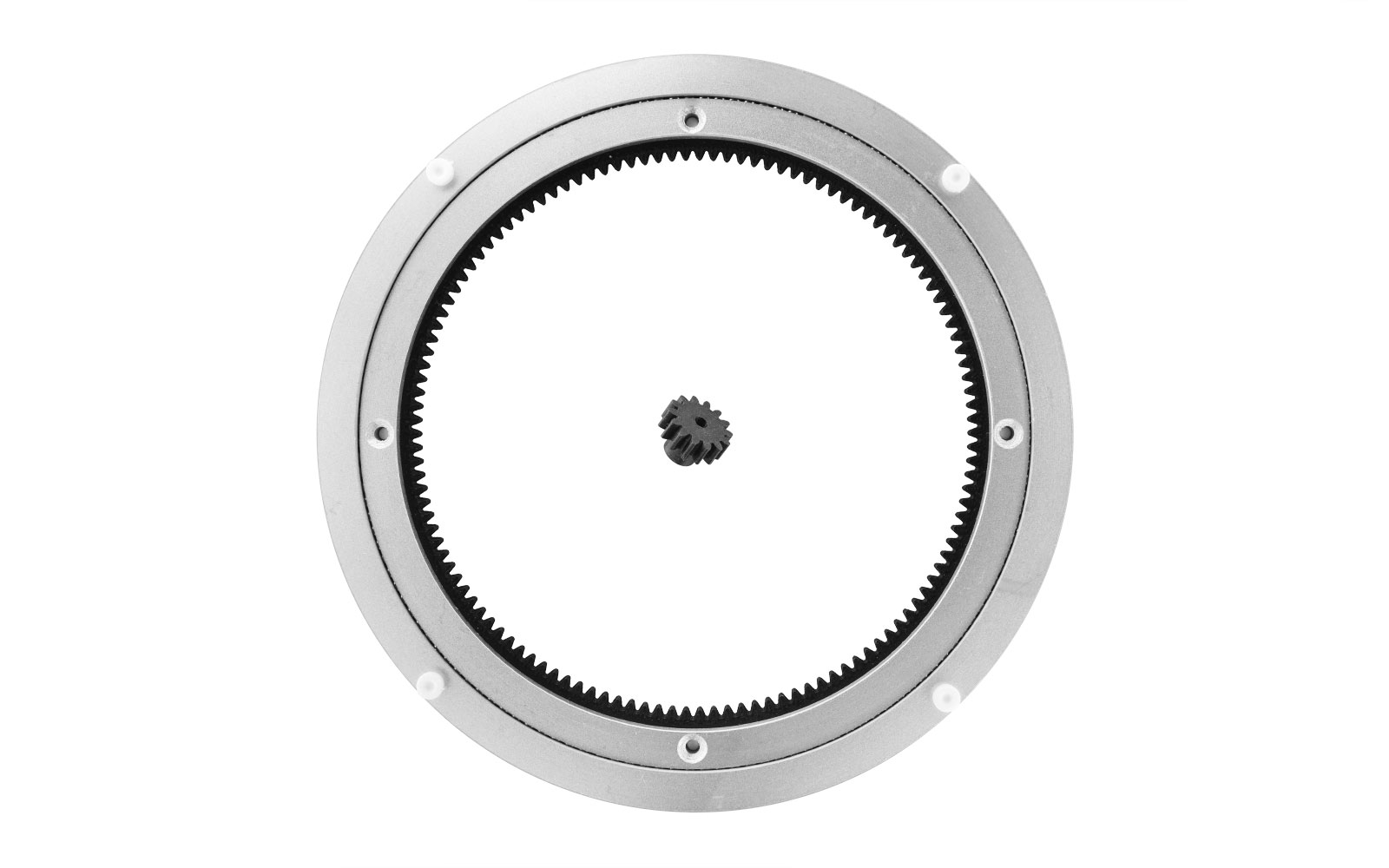
The gear ratio is 1:9 which is a good start. The inner and outer ring have a tad bit of play but for an inexpensive prototype it should be good.
Drive train 🚤
For the spur the best choice is a common stepper motor e.g. used in 3D printing. With a form factor of NEMA 17, 100 steps at 1.8°/step, 12 volts and 1 amp we should be good to go. Since those motors usually support micro steps up to 3.200 steps per revolution there we could already support 360°/1:9/3.200 steps = 0.0125° per step. Still with 45 arc seconds there is way to improve.
Next we want to have the whole drive train running smoothly. That said we could incorporate a drive belt with a pulley. Besides giving some smoothness to the spur it'll add another level of transmission. The 20:60 drive belt from the 3D printing field looks good:
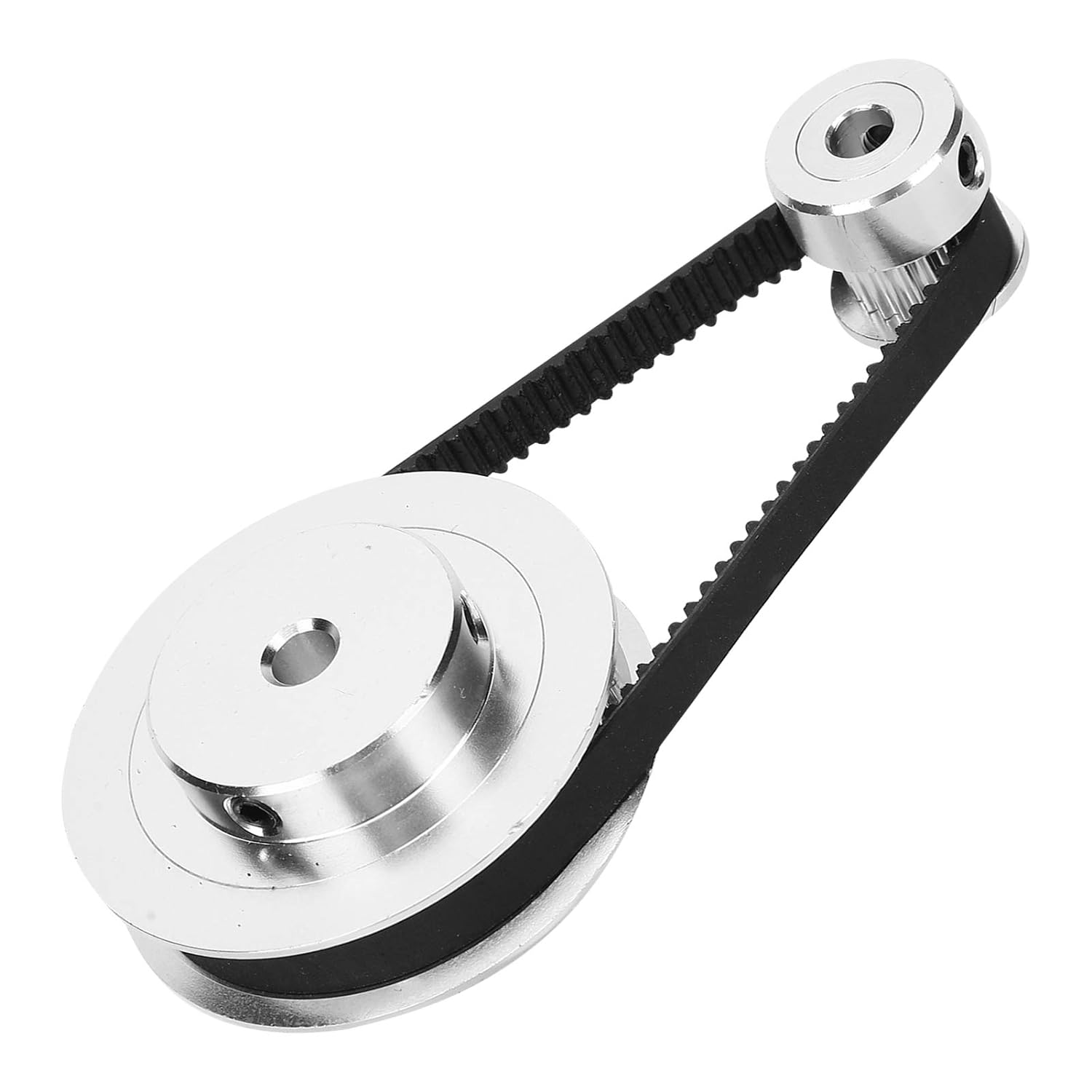
With 1:3 transmission and the 1:9 transmission from the turntable we are now at a 1:27 gear ratio. Awesome! 🎉 Filling in the numbers one motor step now moves our platform by 0,0041666667° or 15 arc seconds!!
Mounting plate
The mounting plate should be thick enough to carry the max load of the turntable. A 3mm aluminum base plate will do for now. We'd need several cutouts:
- Primary stepper motor
- Primary stepper motor adjustment
- Secondary stepper motor
- Secondary stepper motor adjustment
- Tertiary stepper motor (aka cheap stepper)
- Tertiary stepper motor adjustment
- Drive belt axis + bearing
- Holes for the outer turntable ring
- Mounting holes for the superstructure
- Cutouts for getting wires forth and back
- Center hole for connecting wires
This basic mounting plate will hold the transmission as well as the electronics to control the whole platform. An almost identical plate will sit on top to give more stability to the axle of the driving belt.
Since we want to allow infinite turns in all directions the wires need to be decoupled from the platform. Thus a center cutout for a slip ring makes great sense:
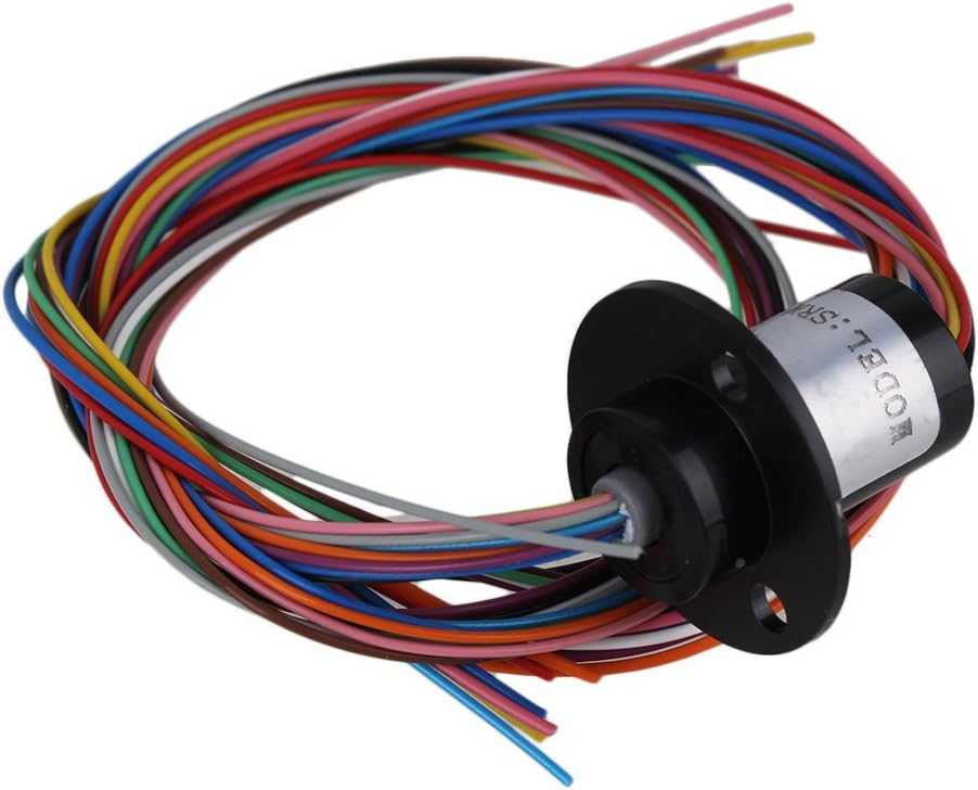
With 12 wires and 2 amp load this might be undersized but will allow us to improve the design later on.
The basic design should look like this:
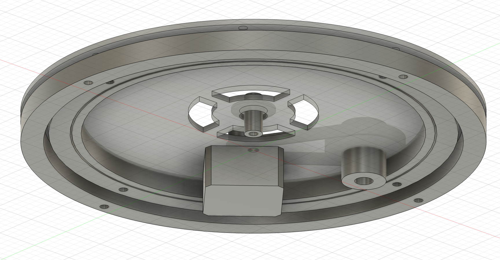
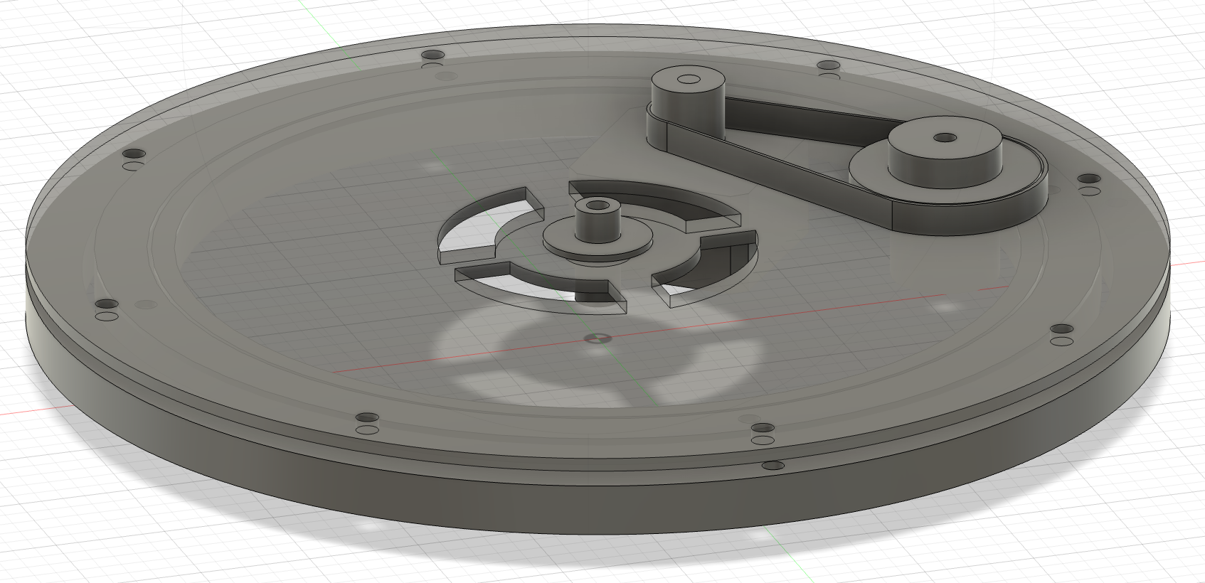
The motor sits under the base plate driving the pulley. With all the cutouts and considerations a first design for the base plate comes to this:
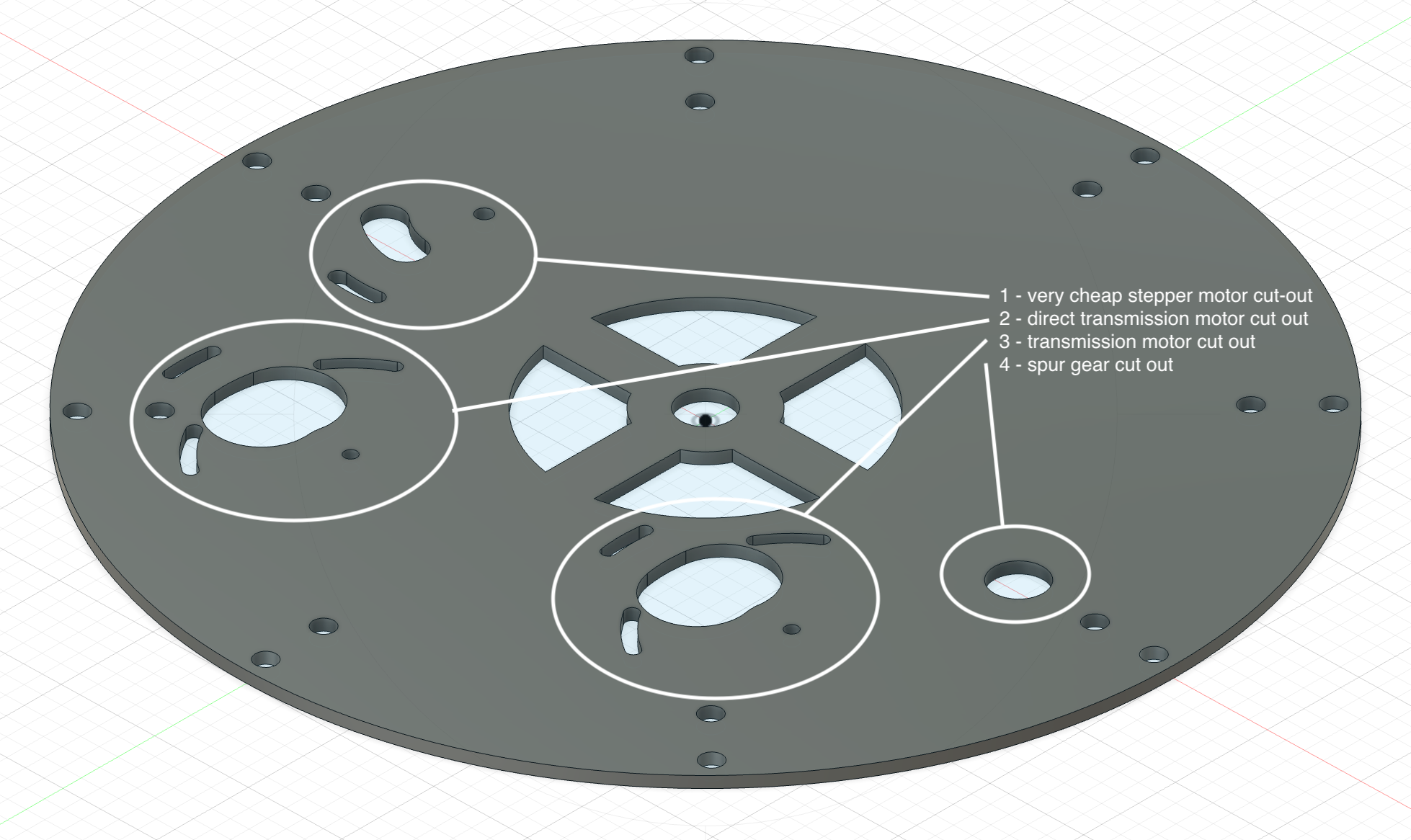
Since the motor sits under the plate and being below zero level, the turntable needs some spacing to the ground which is easy to achieve using some 20mm thread connectors and levelling screws.
Basically there are 4 specific cutouts for motors:
- Cut out for the very cheap stepper of type 24BYJ48. Only one side is fixed, the motor itself can be rotated some degrees in order to adjust the distance to the turntable.
- Cut out for a NEMA 17 motor. Again only one side is fixed allowing the motor to adjust.
- Same as 2 but not meant to be directly driving the turntable (although with a spur gear with a larger diameter this should work). The adjustment mechanism works as fastener for the belt.
- Cut out for the spur gear holding a 13mm axial bearing for smooth transmission of the spur gear.
Controller(s) and wiring
As a main controller we'll use an ESP32 development board (ESP32-WROOM-32). It's not a power horse but provides Bluetooth and WiFi. The stepper motors need a dedicated driver (A4899) separating the 3 volts of the main controller from the 12 volts of the motor.
Controlling the motor
We'll use some simple Arduino code for running the platform. The speed stepper library (https://github.com/Stan-Reifel/SpeedyStepper) does a pretty got job getting us jump started.
Let's do some cool things...
Now that we have a basic understanding of how to move this motor let's get rid of the connected data wire and use BLE (Bluetooth Low Energy) to control the movement of this little beast.
After setting up the BLE server and this awesome iOS app nRF Connect (https://apps.apple.com/de/app/nrf-connect-for-mobile/id1054362403) - which is btw also available for other platforms - we can connect to the controller and use the published service to send movements in steps to the platform.