PWM MOSFET Driver with a Teensy 4.1
Every wanted to drive a more demanding load with a Teensy? Search no more. A lot of motors you could use for various applications can be controlled using pulse width modulation (PWM).
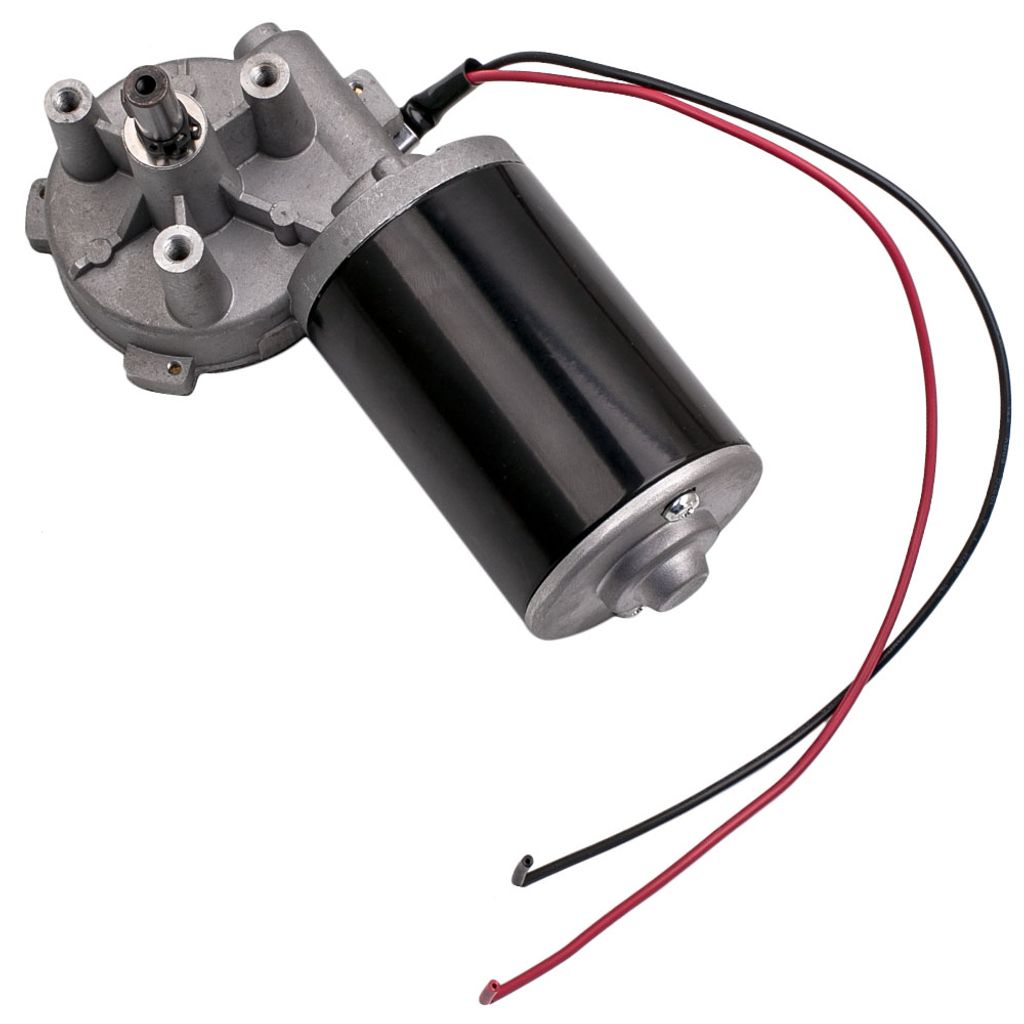
Let's take this DC motor. It comes with some decent torque and runs at 24V drawing a max current of 3A.

Its RPM are easily controlled with an according PWM driver you could be for some bucks from blue A. However if we want a more technical approach it is worth to spend some time to understand how to control that from a board like a Teensy.
There are two things we need to take into consideration:
1) Output Voltage of the Teensy (3.3V or 5V) is far from being sufficient in order to operate this motor. Currents around 40mA do not help at all as well. Thus we need a second voltage supply with enough juice to get the motor going.
2) When the motor continues to rotate (even for a tiny bit) without any voltage being provided we need some sort of flywheel in order not to harm the Teensy.
That said we need some sort of switch (transistor) with a considerable low Gate voltage but higher specs related to the Source to Drain Voltage. Usually this is a good terrain for MOSFETs (Metal-Oxide-Semiconductor Field-Effect Transistors). Since we do not want to bother about the whole circuit itself we take convenience road and buy a MOSFET driver board (e.g. MOSFET Drive Module 5V-36V 15A (max. 30A) 400W). It is good enough to drive our motor - at least we hope so.
Setup
The setup is really simple. The Teensy goes to the USB port as usual. GND of the Teensy and the Driver Module go to GND. The select one PIN of the Teensy to go to the PWM input of the Driver Module.
The Driver Module itself has V(in) and V(out). The motor goes to V(out) and the a DC power supply goes to V(in). The DC power supply is set to 24V and a max current of 3A.
We set the following code in Teensyduino:
const int pwmPin =  12;
const int dutycycle = 128;

void setup()   {
  pinMode(pwmPin, OUTPUT);
}

void loop()
{
  analogWrite(pwmPin, dutycycle);
}
Since analogWrite does expect an 8 bit duty cycle as second parameter, 128 will give us a 50% duty cycle. Compile and Upload!
Hooking up the oscilloscope to Pin 12 shows a square wave with a 50% duty cycle.
Regulator
This setup is a little bit too static so we add some spice. With a potentiometer we can modify the duty cycle of the signal which will result and slower or faster rotating motor.
Therefore we connect the 3V pin of the Teensy to the input of the potentiometer. GND goes to common GND and the output of the potentiometer (the middle pin) goes to Pin 19 on the Teensy.
So what we are doing now is reading an analog signal converting it to an according output value and output to the Drive module.
const int pwmPin =  12;
const int potPin = 19;
int val;
float un = (float)255/(float)1024;

void setup()   {
  pinMode(pwmPin, OUTPUT);
  Serial.begin(38400); //debug
}

void loop()
{
  val = analogRead(potPin);
  Serial.print("analog in is: ");
  Serial.print(val);
  Serial.print(" - duty cycle: " );
  Serial.println((int)((float)(un)*val));
  delay(250);
  analogWrite(redPin, (int)((float)(un)*val));
}
This code is rather simple as well: the analogRead value is in the range from 0-1024 (since the Teensy samples at 10 bit).
Calculating 255 / 1024 * val downsamples the value to the range 0-255 we need for the PWM output.
Compile and Upload time again!
Turning the potentiometer actually controls the motor speed, nice! Frankly, this could have been achieved without heave ARM CPU armoury but well, why not bother. 😬
Considerations
MOSFETs dissipate a reasonable amount of heat. For 24V and 3A max current this is 72W power. Usually MOSFETs are mounted on a suitable heatsink. Having played around with this setup, don't touch the MOSFETs right away, you might get some burn marks! 🔥