
Homebrew Motorola 68000 Reset Circuit
The RESET Circuit
A 555 timer is great! There are many applications and the book 'Much ado about nothing' is a great read if you want to know how this IC came to life.
The easy way
Per the documentation, reset should be pulled low at least 100ms in order to guarantee a clean recovery. Let's make things easier and use a 555 timer in monoflop configuration:
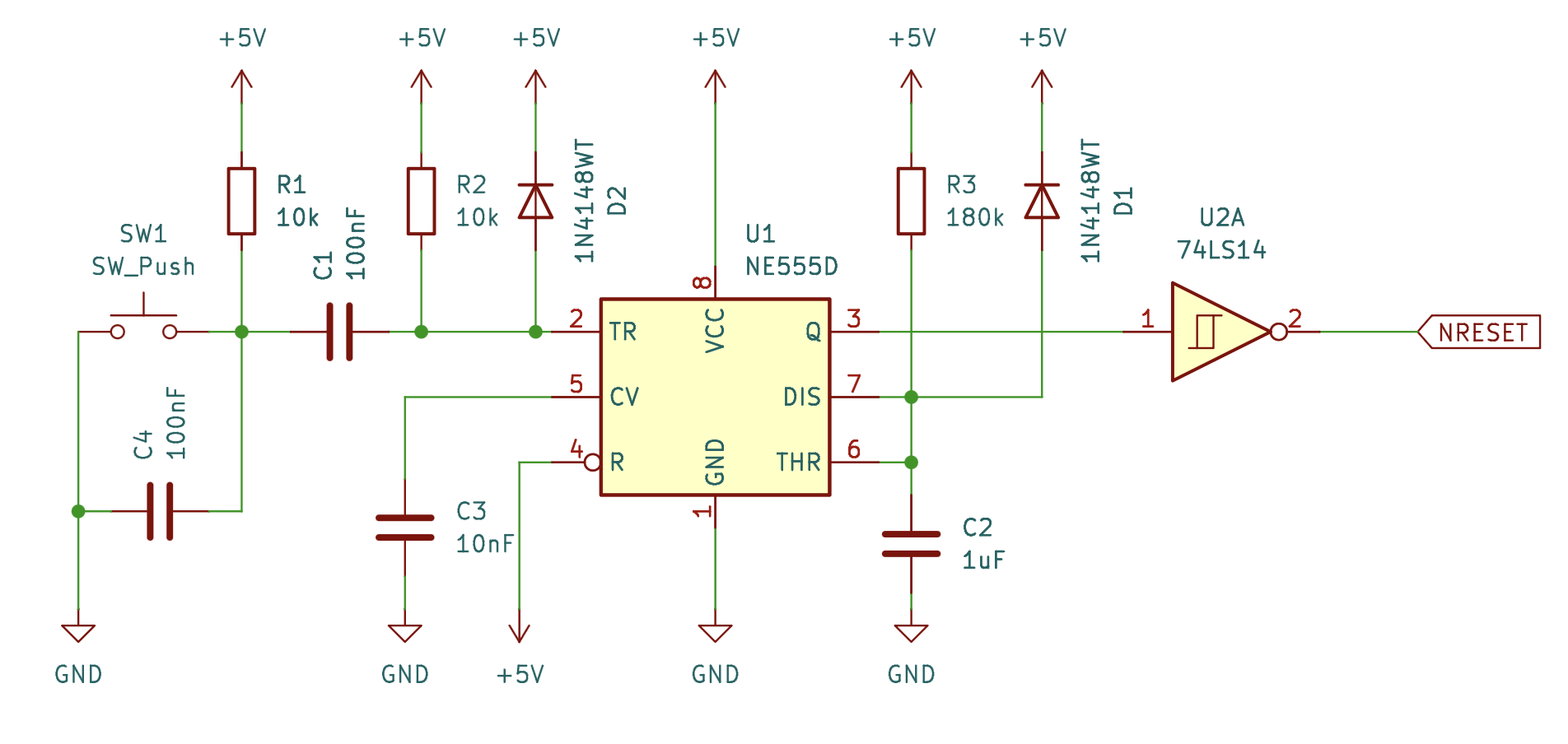
Left side: Push button + edge shaping (trigger conditioning)
What this does
• R1 (10k) pulls the button node HIGH when not pressed
• SW1 pulls the button node LOW when pressed
• C1 (100 nF) AC-couples the button node to the 555 trigger
• R2 (10k) pulls TRIG (pin 2) HIGH normally
Resulting behavior
• When you press the button (High → Low at BTN):
• C1 couples a short negative pulse into pin 2
• Pin 2 briefly goes below 1/3 VCC
• This triggers the 555 once
• While you keep holding the button:
• TRIG returns HIGH via R2
• The 555 is not retriggered
This is why the pulse length is now independent of button press duration.High-level function
• A push button or power-up edge creates a short trigger pulse
• The NE555 runs as a monostable (one-shot)
• The monostable generates a ~200 ms HIGH pulse
• A 74LS14 Schmitt inverter inverts and cleans this into a ~200 ms LOW reset pulse (NRESET)
This guarantees:
• One reset pulse per trigger
• Reset length is set by R3 and C2
• Reset does NOT depend on how long the button is held
Middle: NE555 monostable (timing generator)
This is the standard 555 monostable configuration.
Pulse width formula
t = 1.1 x R3 x C2
t = 1.1 x 180k x 1uF = approx. 198 ms
Right side: Schmitt inverter + reset output
What this does
• Inverts the 555 output:
• 555 HIGH (200 ms) → NRESET LOW (200 ms)
• Schmitt trigger:
• Sharp edges
• Noise immunity
• Clean reset waveform for downstream logic
Power-on behavior
On power-up:
• C2 starts discharged
• The 555 may produce a pulse depending on ramp rate
• With this topology, you often get an automatic reset pulse at power-up
If you need to guarantee a reset on slow ramps, you can add:
• RC delay on pin 4 (RESET), or
• A proper voltage supervisor IC
The diode across R3 is for faster recovery on power-off. This discharges C2 quickly when power drops, ensuring the next power-up always generates a proper pulse.
D1 - timing capacitor discharge
What it fixes
• Provides a fast discharge path for C2
• Ensures clean behavior on:
• Power-down
• Rapid retrigger attempts
• Brown-out conditions
This improves robustness and repeatability (but was not the cause of bounce).
C4 - debounce capacitor
What it fixes
• Suppresses mechanical contact bounce
• Slows the button edge slightly
• Prevents multiple High→Low transitions from being coupled through C1
This directly addresses the most common cause of “double fire”.
D2 - clamp diode
What it fixes
• Clamps the positive spike on TRIG when the button is released.
• Prevents the AC-coupled network (C1) from creating a second effective trigger.
• Greatly reduces false retriggering.
Can this be done with just analog components?
Yes, it can! With only using transistors, resistors and capacitors, this can be achieved as a completely analog circuit also. 'The Art of Electronics' (Page 77ff) shows how to do it. (It's an awesome book by the way)
Can this be made better?
There is one improvement to me made: whenever we reach sufficient supply voltage we can kick the reset procedure and let the CPU run.
Still, the 555 comes in handy, but we need a comparator to measure if we reached our reference voltage already. This is a job for the LM393 aaaand we use a Schmitt trigger for clean signal:
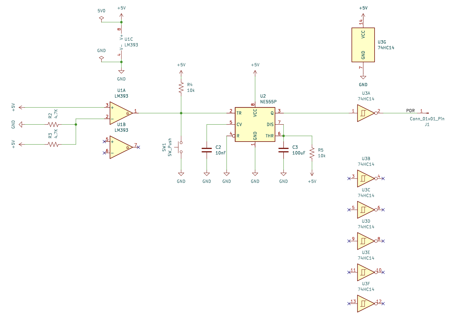
Power on Reset (POR) goes to /HALT & /RESET and lets the CPU restart.